Family 1 is the family of lines and angles and in just this short time you can interpret all of the figures in this family as soon as you know one other fact -- that the only angles allowed for straight lines are: horizontal, vertical, and 45° to the horizontal (up or down).
Those basic angles look like this when drawn as figures:

Note that in Example 3-4, the vertical down line is drawn as dashed. You’d think that any vertical line has zero AoA and therefore should be drawn as a solid line, but in the Aresti drawing conventions, the line style for vertical lines indicates what it took for the airplane to get onto that line. Example 3-4 begins with the airplane in horizontal, upright (positive AoA) flight. To achieve a vertical down line from upright flight, the pilot would have to push on the stick, or apply negative AoA to force the airplane’s nose down to the vertical. Hence the dashed vertical line. After flying straight down for a bit, the airplane would indeed have zero AoA, as intuition would suggest, but the Catalogue’s drawing convention simply requires that the entire line will be drawn as dashed.
For lines other than vertical, the line style indicates the AoA after the airplane has established itself on the line. For example, in the exit from the vertical line up (Example 3-3 shown above), the pilot had to use a negative AoA (push) to transition from the vertical line to the upright horizontal exit line, but the exit line is drawn as a solid line because once established on that line, positive AoA would have to be maintained to hold horizontal flight.
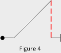
Browsing through Family 1, you will notice next that all these figures are drawn with sharp corners where the flight path changes angle. Physics (inertia) prevents an airplane from actually flying a ‘square’ corner, so again the catalogue has adopted a drawing convention, which dictates how looping lines are to be drawn. Convention: All looping lines less than 180° in extent are drawn as hard angles. Looping lines of 180° or more, are drawn as actual looping lines. Thus, when we look at this Family 1 figure (Figure 4) which is drawn with all hard angles on paper,

what we would really see when the airplane flies is, a 1/8 (45°) looping line from horizontal to upright flight on a 45° line, followed by a 135° outside loop down to the vertical, followed by a 1/4 (90°) inside loop back to upright, horizontal flight. A pilot who tried to fly this figure to make it look exactly as it does on paper, would actually be flying it incorrectly.
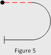
On the other hand, Figure 5, which is from Family 7,a one-half (180°) loop down starting from inverted flight, would appear in the air exactly as it appears on paper. As a quiz on what we’ve learned so far, see if you can describe what you would observe if watching an airplane fly Figure 5. Time’s up. You’ve learned that Figure 5 begins at the dot. The dashed line tells you the airplane is in horizontal inverted flight. The pilot then departs horizontal flight by applying a positive AoA (solid line) to the airplane and flying an inside (positive) half loop down. Following the half loop, the airplane exits in horizontal upright (positive AoA) flight in the opposite direction from which it began. Finally, the short vertical line indicates that’s the end of this figure.


