By Brian Howard
Previously in this tutorial you learned that to be legal for competition, all aerobatic figures must be constructed using only the base figures from Families 1 through 8 and rotational elements from Family 9 found in the Aresti Aerobatic Catalogue (Condensed). You also learned the meaning of 13 symbols (notations) used in the Catalogue to represent those elements. Continuing the Aresti tutorial will teach you seven additional notations (all dealing with the complementary rotational elements found in Family 9) and show you how to combine the components from the Catalogue into real-world figures which are immediately recognizable to any aerobatic pilot in the world, regardless of their native spoken language.
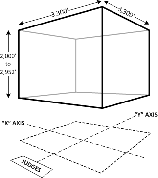
Before we can start drawing figures, however, you need to understand a little about how aerobatic competitions work. As with most any sport, aerobatic competitions have their own “playing field,” except in aerobatics it’s three-dimensional and called a “box.” The aerobatic box is 3300 feet on each horizontal side (it’s actually 1000 meters, but in the metric-challenged U.S. we use 3300 feet) with a vertical height depending on the category of the competitor. Not surprisingly, higher category competitors are allowed to fly closer to the ground than the lower category pilots. During a competition flight, the airplane must remain within this box or the pilot will receive penalty points as a consequence of failure to do so. Figure 1 depicts the general layout of an aerobatic box.


